Subsea control modules · LNG & cryogenic process control · low-temp instrumentation

Control Systems Engineered for the Extremes, Subsea and Cryogenic Applications

We engineer control systems for rotating machinery and process applications at the extremes of operating environment, subsea installations to 3,000 meters and cryogenic process systems to -196 degrees C, where standard industrial control equipment simply cannot function.
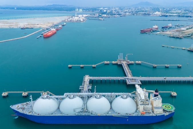
LNG carrier with cryogenic storage tanks at a terminal

Control

Subsea and cryogenic control for the industry's most extreme service

Subsea rotating machinery and cryogenic process equipment are two of the most demanding control engineering environments in industrial service, and the fundamental challenge is the same: standard control equipment, sensors, valves, actuators, wiring, enclosures, was designed for ambient temperature, surface pressure. In subsea applications, equipment operates at hydrostatic pressures that can exceed 300 bar, in near-freezing seawater, with no maintenance access between planned intervention campaigns. In cryogenic service, temperatures below -100 degrees C cause standard elastomeric seals to lose flexibility, carbon steel to become brittle, and standard electronic components to exceed their rated operating range.


We bring the materials engineering, electronic component qualification, and control system design expertise to engineer systems that are genuinely reliable in these extreme environments, not systems designed for ambient conditions and adapted with post-design reviews. Our subsea and cryogenic designs begin with the environmental requirements and work outward from them to select qualified materials, components, and designs, and we develop the control logic to IEC 61131-3 so proven strategies deploy on the platform that best fits your lifecycle, with full logic access and no license walls.
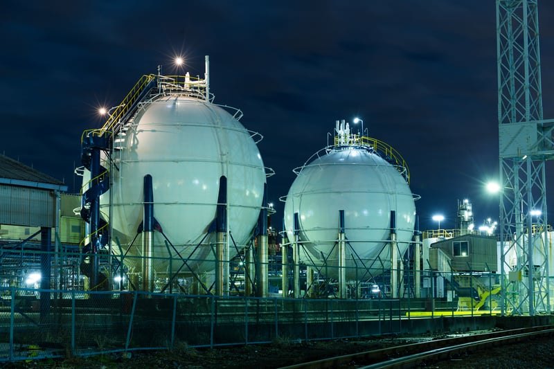
LNG spherical cryogenic storage tanks at night

The Problem

In these environments, a failure is out of reach

The consequences of a control system failure in an extreme environment are dramatically magnified compared to surface applications. A subsea control failure on a compressor at 1,500 meters means a production shutdown that will not be resolved until an ROV intervention or a full subsea workover, potentially $5–20M for the intervention alone, before the deferred production value. In a cryogenic LNG application, a valve actuator failure at -160 degrees C means a plant shutdown while the valve is warmed up, repaired, and returned to service, a multi-day event with significant production loss.


The failure modes are specific to the environment. Subsea electronics fail from hydrostatic pressure differential deformation, seawater ingress through inadequate pressure compensation, low-temperature de-rating, and biofouling. Cryogenic components fail from brittle fracture of carbon steel, loss of seal flexibility, ice formation on external valve surfaces, and thermal-cycling stress. Standard industrial design practices do not address these: they require the specific engineering responses we have developed through real experience in these environments.

Capabilities

Sub-sea & cryogenic control capabilities

From cryogenic temperature-rated components through pressure-compensated subsea electronics and topside interface panels, control systems qualified for the actual operating environment.

Cryogenic Temperature-Rated Control Components

We specify and qualify control system components for cryogenic service, covering the full operating range from ambient to -196 degrees C for liquid nitrogen service. Component selection addresses materials of construction (stainless steel, Invar, and aluminum alloys for low-temperature ductility), electronic component temperature de-rating (many commercial electronics are rated only to -40 degrees C, requiring specifically qualified low-temperature components for colder service), and seal material selection (PTFE, Viton Extreme, and other elastomers qualified for low-temperature flexibility). Material qualification testing results are documented in the component data package.

Subsea Hydraulic Actuator Interface

Subsea valve actuators are typically hydraulic, with control fluid supplied from the topside hydraulic power unit through a flexible umbilical. We design the topside hydraulic power unit, the umbilical interface panel, and the subsea valve actuator control logic as an integrated system, ensuring the hydraulic supply pressure and flow capacity at the topside end is adequate to operate all subsea actuators simultaneously at the rated actuation speed, accounting for the hydrostatic head and umbilical pressure loss at the rated water depth.

Subsea Control Module Design

We design subsea control modules for installation on subsea trees, manifolds, and equipment modules at water depths to 3,000 meters. The design addresses hydrostatic pressure compensation (using oil-filled, pressure-compensated electronics housings), connector and penetrator qualification for long-term subsea service, corrosion resistance in seawater environments, and the reliability requirements imposed by long intervention intervals, typically 2 to 5 years between planned interventions.

ROV Interface Design

Subsea equipment that may require manual intervention by an ROV must provide accessible interface panels that an ROV manipulator arm can engage. We design ROV interface panels with ROV-operable override valves, electrical wet-mate connectors, and mechanical override provisions for subsea valve actuators, allowing trained ROV operators to override the control system and operate individual valves manually during intervention campaigns. ROV interface design follows the industry standards for underwater tool interface and connector compatibility.

Pressure-Compensated Electronics Enclosures

Standard electronics enclosures cannot withstand deep-water hydrostatic pressure without deformation that damages internal components and connections. Pressure-compensated enclosures maintain internal pressure at or slightly above the external hydrostatic pressure through a compensator mechanism, a flexible membrane or piston that transmits external pressure into a compatible, non-conductive internal fluid, eliminating the pressure differential that would otherwise crush the enclosure. We design and qualify pressure-compensated electronics enclosures for each application's rated water depth, with hydrostatic pressure testing to 1.5 times rated water depth as standard acceptance testing.

Umbilical Signal Transmission

Control signals, power, and hydraulic fluid are transmitted from the topside control system to the subsea equipment through an umbilical, a bundled cable and hydraulic hose assembly that may be several kilometers long. We design the topside-to-subsea signal transmission system accounting for umbilical signal attenuation, electrical noise in long cable runs, and the topside hydraulic system pressure and flow requirements imposed by the umbilical length and the subsea actuator demand. Umbilical termination panels at both the topside and subsea ends are designed and tested as part of the control system scope.

Cryogenic Valve Actuator Control

Control valves in cryogenic service, LNG, liquid nitrogen, liquid oxygen, and liquid argon, require actuators and position feedback devices qualified for operation at the cryogenic service temperature. We specify cryogenic-qualified pneumatic and electric actuators, position transmitters with low-temperature-rated electronics, and positioner designs that can operate reliably with the reduced flexibility of cryogenic-compatible seal materials. Ice prevention on external valve and actuator surfaces, through insulation, heat tracing, or dry nitrogen blanket, is also addressed in the installation design.

Topside Interface and Control Room Panel Design

The topside interface panel for a subsea control system integrates all subsea monitoring signals, hydraulic power unit controls, umbilical junction, and the SCADA/DCS interface into a single operator workstation for subsea field control. We design topside interface panels that provide the operator with complete visibility into the subsea equipment status, valve positions, pressures, temperatures, and alarms, from a topside control room, with remote operation capability for all controllable subsea functions. Interface design follows industry standard subsea control system architectures where applicable.

Why Innova Technologies

Engineering that starts from the environmental requirement, not the standard catalog

Extreme-environment control systems cannot be designed by substituting certified low-temperature components into a standard design. The environmental requirement drives every design decision, from materials to architecture.
Materials Engineering Expertise
The most common failure mode in extreme-environment control systems is material selection error, components rated for the operating temperature range in standard test conditions but failing in the combined thermal, pressure, and chemical environment of the actual installation. Our materials engineering review evaluates every component’s rated operating environment against the actual service conditions, low-temperature ductility data, elastomer flexibility at cryogenic temperatures, coating compatibility with cryogenic fluids, and electronic component temperature de-rating, and documents the qualification basis for every component in the material qualification register.
Subsea Field Experience
We have delivered topside interface and control systems for subsea rotating machinery and process equipment projects, working alongside subsea equipment manufacturers and installation contractors to integrate the control system with the subsea equipment design. Our engineers understand the specific requirements of subsea projects, intervention campaign planning, umbilical design coordination, ROV interface requirements, and the documentation and testing standards required by offshore class society regulations, from real project experience.
Cryogenic Process Knowledge
Our control engineers have experience with LNG liquefaction, LNG regasification, liquid industrial gas production, and cryogenic storage and transfer applications, the primary industrial applications for cryogenic process control. This process knowledge informs both the instrumentation selection (compatible with cryogenic fluid characteristics) and the control logic design (addressing the specific behavior of cryogenic process systems, including insulation requirements, thermal soak-out procedures, and cool-down rate controls).
Custom Qualification Testing
Standard off-the-shelf control components are tested to standard temperature ranges that may not cover extreme-environment service conditions. For components where standard qualification testing does not cover the required service temperature or pressure, we perform or commission custom qualification testing, subjecting prototype assemblies to the actual service conditions, to establish a qualification basis for the selected component. Custom qualification test results are documented and provided as part of the project documentation package.
Long-Term Supportability Planning
Subsea and cryogenic control systems often operate for 20 or more years between major interventions. We design these systems with long-term supportability specifically in mind, selecting components with long product lifecycles, designing modular replacement provisions that allow subsystem upgrades without complete system replacement, and providing detailed spare parts lists with long-lead-time component identification. Our open-architecture design approach, open, documented, maintainable logic on commercially available hardware, lets the control system be maintained and upgraded over its service life without dependence on any single hardware supplier’s product continuity.
Equipment and licensors we integrate

TechnipFMC

Aker Solutions

Baker Hughes

OneSubsea

Air Products

Linde

Chart

Nuovo Pignone

Technical Resources

Engineering documentation for sub-sea & cryogenic control

Engineering documentation developed from real subsea and cryogenic control system projects, giving your team the technical basis for qualification and specification.

What Happens During Control System Commissioning?

Control Panel Design for Harsh Industrial Environments

The Future of Turbomachinery Control Systems

FAQ

Frequently asked questions

What is the deepest water depth you have provided control systems for?
We have designed topside interface and control systems for subsea equipment projects at water depths in excess of 1,500 meters, working in coordination with the subsea equipment manufacturer and the offshore installation contractor. Our topside scope typically covers the topside hydraulic power unit, the umbilical junction panel, the topside control panel, and the SCADA/DCS interface, while the subsea-rated hardware (subsea control modules, subsea valves, and umbilical) is supplied by specialized subsea equipment vendors with whom we coordinate design interfaces. For deeper water applications, we collaborate with subsea engineering firms as required by the specific project’s technical requirements.
Qualification of a control panel enclosure for cryogenic service involves: material review to confirm that all structural materials maintain adequate ductility at the rated minimum temperature (stainless steel grades, aluminum alloys, and some carbon steels with Charpy impact test data are typically acceptable), seal and gasket material qualification for retention of compression set and sealing function at the rated temperature, electronic component review and de-rating analysis to confirm all active components are either rated by their manufacturer for the required temperature range or have been tested at it, and thermal testing of the assembled enclosure at the rated minimum temperature to verify the materials and components perform as expected. We perform this qualification program for every control system designed for cryogenic service and provide the qualification documentation as part of the project deliverables.
The subsea control module (SCM) is the electronics and hydraulic interface assembly physically installed on the subsea equipment, on the subsea tree, manifold, or equipment module, at the rated water depth. It contains the local electronics for hydraulic valve control, sensor signal conditioning, and communication with the topside system through the umbilical. The topside interface panel is the surface-located control panel that provides the operator interface and the connection to the SCADA/DCS system. It houses the topside hydraulic power unit controls, the umbilical termination, the communication system that links to the subsea electronics, and the operator graphic displays for subsea equipment status and control. Our typical project scope is the complete topside interface panel and the integration coordination with the subsea equipment manufacturer’s subsea control module.
Cryogenic process equipment undergoes significant thermal cycling, from ambient temperature during maintenance warm-up to cryogenic operating temperatures during operation. This imposes stress on all materials and components due to differential thermal expansion and contraction. We design cryogenic control systems with thermal cycling in mind, using flexible conduit and cable connections that accommodate differential expansion, avoiding rigid mechanical connections between components at significantly different operating temperatures, and selecting materials with compatible coefficients of thermal expansion. For applications with frequent thermal cycling, such as LNG refueling equipment that cycles from ambient to cryogenic on every use, the thermal cycle fatigue life of critical components is evaluated and documented in the design qualification.
Subsea-to-topside communication systems use electrical communication over the umbilical cable’s electrical conductors, with protocols designed for the long cable lengths and the specific reliability requirements of subsea systems. Common protocols include serial communication over shielded twisted pairs (with noise filtering to address interference in long umbilical cables), Ethernet over fiber optic conductors in the umbilical (for higher bandwidth and noise immunity), and acoustic communication (for short-range, low-bandwidth applications where a hardwired umbilical is not available). We design the topside communication interface based on the project’s umbilical configuration, data bandwidth requirements, and the communication protocol used by the subsea equipment manufacturer’s SCM.
Related Capabilities

Protective functions that work alongside vibration monitoring

Vibration protection is one of several machinery protective functions that benefit from being engineered and maintained together. When Innova modernizes a machine’s controls, related protective measurements can be brought into the same platform, HMI, and historian, each kept appropriately independent of the primary control path where the protection philosophy requires it.
Speed Measurement & Protection
Overspeed is among the most consequential events for any rotating machine, so speed protection is typically implemented independently of the primary control path. Innova Technologies provides independent overspeed detection and speed sensing that feeds protective trip logic through dedicated channels, so a control fault cannot disable the protective function. Speed inputs are monitored continuously with signal-validity checking, and trip actions are annunciated with first-out capture so operators can see what initiated a trip. The specific redundancy and voting arrangement is engineered to the machine and the applicable protection requirements.
Exhaust Temperature Measurement

Exhaust temperature and its distribution around the turbine are a practical indicator of combustion health, so multi-thermocouple exhaust monitoring is a common part of the protective scope. Innova Technologies integrates arrays of exhaust thermocouples to measure both average exhaust temperature and the spread between individual sensors, which can reveal a burner or fuel-nozzle problem before it becomes damaging. Alarm and protective action can be configured on excessive spread as well as on high average temperature, with individual thermocouple failures detected and annunciated. Presenting this data in the same HMI and historian as the vibration and speed functions gives operators a single, consistent view of machine condition.

Where standard engineering stops, we start

Whether you’re controlling rotating machinery at 2,000 meters subsea or managing a cryogenic process at -160 degrees C: we engineer control systems that work in the real environment, not just in the specification.

Featured

Open, documented, maintainable control.

IEC 61131 standardized logic your team can support without OEM lock-in.

Don’t see your industry?

Your machinery application is likely in our scope.

If your equipment runs and your downtime costs more than the controls do, let’s talk

Single-source

One team, drawing to startup.

Engineering, fabrication, installation, and commissioning under one contract.
FORMERLY PETROTECH

A New Name for the Company We've Become.

SAME PEOPLE.
SAME ENGINEERING EXPERTISE.
BROADENED HORIZONS.

A MESSAGE FROM JOHN KAZOUR, CEO

Welcome to Innova Technologies

To our customers and partners,

For more than 50 years, our team has helped customers keep critical operations running. We built our reputation as Petrotech by taking responsibility for control systems on important rotating machinery.

As more industries came to us with similar challenges across power generation, compression, and hydro applications, our engineering team kept finding ways to solve them. Eventually, the business outgrew the Petrotech name.

We are entering our next chapter as Innova Technologies. The new name reflects the full scope of our work as a rotating machinery control systems specialist. We engineer controls around the machine, deliver complete projects from design through commissioning, and provide support that stays with the problem until it is solved.

Our name is changing, but the people, engineering experience, and commitment behind the work continue. Our responsibility to active projects and installed systems carries forward under the Innova Technologies name. Your current contacts remain the right place to start, and we will communicate directly if an administrative record requires an update.

We appreciate the trust you have placed in us over the decades, and we look forward to continuing that work as Innova Technologies.

John Kazour

CEO, Innova Technologies